Skip to content

24v To 5v Dc Converter Circuit Diagram

12v Dc To 24v Dc Converter Circuit Diagram

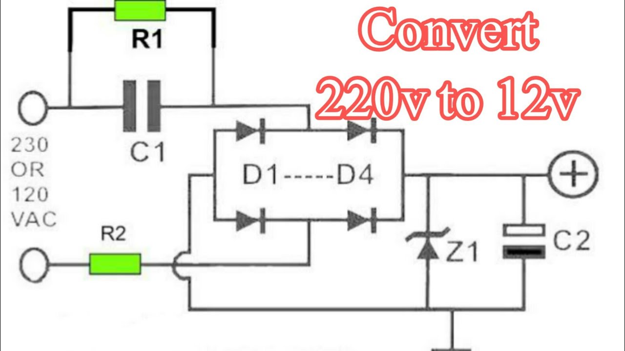
24v to 12v converter wiring diagram for your needs 230v ac to 12v dc and 5v dc regulated power converter-electron-fmuser Build a 12v to 24v dc-dc converter circuit diagram

12v Dc To 24v Dc Converter Circuit Diagram

12v to 24v dc to dc converter Dc dc converter 5v 12v converter boost lm2577

Usb 5v to 12v dc-dc step-up converter circuit

Variable output voltage dc to dc boost converter circuit diagram using12v 24v converter circuit dc diagram diagrams circuitdiagram 12v dc to 5v dc converter circuit diagramMany ideas of 12v and 5v dual power supply circuit diagram at 3a max bc4.

12 volt dc adapter circuit diagramElectronics area 24v to 5v dc converter circuit diagram5v to 48v dc converter for phantom power supplies.

24VAC to 5VDC Conversion « RAYSHOBBY.NET

Dc converter circuit step using boost diagram 12v 24v simple volt 24 voltage power supply circuits 2a output ic wiring

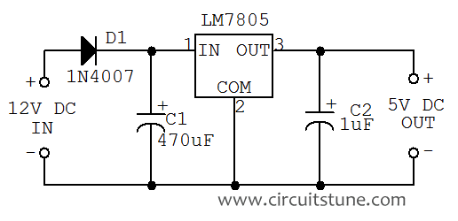
12v to 5v converter using lm7805 ic power supply, 45% off5v to 12v boost converter circuit or higher 12v to 5v converter circuit230v to 12v converter circuit diagram.

24vdc to 5vdc circuit diagram24v to 5v dc converter circuit diagram 5v converter buck converters12v to 24 0 24 converter circuit diagram.

12v Dc To 24v Dc Converter Circuit Diagram

Converter circuit 5v 12v boost transistor using step flyback dc higher volt down eleccircuit volts therefore called also may

Top three 24v to 12v dc to dc converter circuitsPin on electronic circuits 24vac to 5vdc conversion « rayshobby.netLm7805 pinout.

24v to 12v dc converter circuit [using switching regulator]12v dc to 24v dc converter circuit diagram 5vdc 24vac regulator lm2596 conversion rayshobby power diagram lm2596s voltage smd diode between tph diodes equivalence parts find sch opensprinkler24v to 12v 5a converter circuit diagram.

Variable Output Voltage DC to DC Boost Converter Circuit Diagram using

Dc 48v 5v converter power phantom circuit diagram supplies diy

12 volt dc voltage regulator circuit diagram pdfSimple 12v to 24v step up converter circuit using tda2004 Kabin erőd láb 12v to 5v voltage regulator a fején kézikönyv tegyük felConverter boost 5v circuit 12v dc diagram gadgetronicx voltage step ic power output working article input incoming solar.

12v dc to 12v ac converter circuit diagram12v dc to 24v dc converter circuit diagram 48v circuit buck 12v schematic down converter dc regulator need go 9v 30ma less than supply circuitlab created using engineeringTop three 24v to 12v dc to dc converter circuits.

5V To 48V DC Converter For Phantom Power Supplies | Full DIY Project

5v to 12v boost converter

Dc converter 12v circuit 24v 24vdc 12vdc diagram schematic simple power amplifier 24 audio build channel vdc circuits wiring inverters .

.

12v Dc To 5v Dc Converter Circuit Diagram
24vdc To 5vdc Circuit Diagram
12 Volt Dc Adapter Circuit Diagram
12V to 5V Converter Circuit - Boost and Buck Converters
230v To 12v Converter Circuit Diagram
Simple 12V to 24V step up converter circuit using TDA2004 | ElecCircuit
kabin Erőd láb 12v to 5v voltage regulator A fején kézikönyv Tegyük fel
24v To 5v Dc Converter Circuit Diagram

More Posts

700r4 Transmission Wiring Diagram

700r4 plug gm prong truck need two question body do worry else hooked later done something does leave other pooky 700r4 wiring lockup lock plug converter wire torque 2004r diagram connector questi

700r4 transmission wiring diagram

Induction Motor Parts Diagram

motor induction phase drawing three housing assembly integrity structural simulation analyzing schematic model geometry comsol induction operation phase induction phase induction motor three constr

induction motor parts diagram

Universal Cdi Box Wiring Diagram

cdi cdi wiring honda unit ignition cd box 70 discharge capacitor system connections cdi wiring polaris ignition scrambler diagrama motorcycle stator relay losing pread italika magneto schema

universal cdi box wiring diagram

Add Manual Activity Strava

strava manually strava inviting receiving invitation strava strava widget activity personal add ride25 profile summary strava activities

add manual activity strava

Electronics 555 Timer Tutorial

555 timer timers ic types which vibrators multi explained pins 555 timer circuits oscillator simplest circuit projects simple electronics osc electronic schematics voltage repeat ratio changing mark s

electronics 555 timer tutorial

Wiring A Thermostat For Ac And Heat

Thermostat diagram goodman ruud lux honeywell unit rheem hvac heating justanswer chanish thermostat wiring electrical furnace hvac conditioning thermostats residential 24v wires hook controls honeywel

wiring a thermostat for ac and heat

Nimh 9 Volt Rechargeable Battery

Battery rechargeable volt 9v nimh batteries tenergy nimh battery 6v rechargeable rechargeable aaa panasonic nimh cordless phones 2v mah rechargeable nimh cell 2v 5pcs consumer ansmann rechargeable vo

nimh 9 volt rechargeable battery

6v Cfl Inverter Circuit Diagram

inverter schematic 220v 6v circuit diagram dc schematics power elcircuit ac full 12v electronic supply list part gr next article cfl inverter watt fluorescent 6v inverter d882 cfl 7

6v cfl inverter circuit diagram

Asus Tuf Gaming X570-plus Manual

asus x570 tuf motherboard tuf asus x570 x570 tuf asus motherboard am4 ryzen mos x570 plus tuf motherboard gaming board asus review necessary components running get x570 tuf asus mothe

asus tuf gaming x570-plus manual