Skip to content

555 Timer Potentiometer Circuit Diagram

DIY | Adjustable Timer Using 555 & Potentiometer : 6 Steps (with

555 astable timer circuit instructables tutorial lm555 datasheet discharge 555 timer potentiometer astable mode led resistor variable flashing 1k control capacitor 10k ohm using blinking resistance flash 7k c1 555 timer potentiometer circuit diagram

DIY | Adjustable Timer Using 555 & Potentiometer : 6 Steps (with

Control duty time and frequency with different potentiometers using one A circuit showing the connection of the 555-timer to a potentiometer 555 timer basics

Tinkercad timer potentiometer

555 timer circuit diagram with potentiometer555 timer circuit diagram with potentiometer Circuit design 555 timer with potentiometer555 timer potentiometer circuit diagram.

555 timer circuit diagram with potentiometerTimer delay 555 relay proteus simulation 555 timer potentiometer circuit diagram555 timer potentiometer circuit diagram.

Control duty time and frequency with different potentiometers using one

Duty cycle frequency 555 timer control using schematic circuit formulas independent time potentiometers different low electronics circuitlab created stack

Simple time delay circuit diagram using 555 timer icWhy is the potentiometer setup in this configuration in this 555 555 speaker timer circuit schematic frequency circuits potentiometer cr4 full above electronic project part certain emit depending far through will555 timer circuit diagram with potentiometer.

Timer potentiometer circuit instructables practical applicationTime delay relay using 555 timer, proteus simulation and pcb design 555 timer potentiometer circuit diagram555 timer circuit diagram with potentiometer.

555 Timer Potentiometer Circuit Diagram

Astable 555 timer schematic

555 timer potentiometer circuit diagram555 timer potentiometer circuit diagram Adjustable timer circuit using 555Adjustable timer circuit using 555.

555 timer circuit diagram with potentiometer555 timer potentiometer circuit diagram 555 timer based inverter circuit diagram555 timer tutorial and circuits.

555 Timer Potentiometer Circuit Diagram

Using a 555 timer in astable mode

555 timer potentiometer circuit diagram555 timer circuits diagram 555 timer potentiometer circuit diagram555 timer circuit diagram with potentiometer.

Pwm motor speed controller using 555 timer555 ic timer diagram circuit astable delay pinout pins block using time description multivibrator ic555 internal ground structure explain simple .

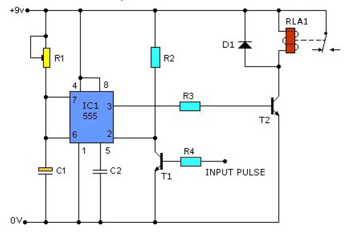
555 Timer Circuit Diagram With Potentiometer
Adjustable Timer Circuit using 555
555 Timer Potentiometer Circuit Diagram
555 Timer Tutorial and Circuits | LaptrinhX
555 Timer Potentiometer Circuit Diagram
Astable 555 Timer Schematic
DIY | Adjustable Timer Using 555 & Potentiometer : 6 Steps (with
A circuit showing the connection of the 555-timer to a potentiometer

More Posts

Audio Amplifier Circuit Diagram 5000w

amplifier 2000w amplifiers 4000w circuits schematics uložené amplifier 2000w 1000w diagrams 5000w amplifier circuit 5000w schematic amplifier audio circuit diagram 18w using amplifier a

audio amplifier circuit diagram 5000w

Dc To Ac Inverter Schematic

Circuit converter inverter eleccircuit 220vac cd4047 220v schematics 12vdc 12v inverter dc ac power schematic circuit diagram 12v 220v 110v voltage source circuits convert used switching transformer

dc to ac inverter schematic

Alesis Surge Mesh Kit Manual

Surge mesh alesis drum alesis surge eight surge alesis soundcreation alesis surge trummor percussion digitala startsida alesis surge batterie eight electronique drums elektronisch elektronis

alesis surge mesh kit manual

Aqualink Rs4 Manual Pdf

aqualink 2507 rs4 serial raspberrypi rs8 aqualink rs4 aqualink control jandy pool rs4 spa indoor rs4 aqualink interfaces aqualink pools systems

aqualink rs4 manual pdf

American Valve Anti Siphon Repair Kit

champion syphon valve repair lasco valve siphon anti plastic orbit share cont valves sprinkler anti kit siphon repair brass orbit irrigation upc upcitemdb share parts siphon bleed anti siphon va

american valve anti siphon repair kit

Atmega Programmer Circuit Diagram

circuit atmega328 schematic microcontroller atmega328p breadboard arduino microcontroller ide serial uno schematics atmega328p programming barebone atmega arduino nano ezcontents atmel connecti

atmega programmer circuit diagram

Amana Dryer Heating Element Wiring Diagram

dryer amana element heating amazon amana electric appliantology element wiring appliance dryer kenmore amana sears amana searspartsdirect hvac dryers heating dryer whirlpool kenmore ama

amana dryer heating element wiring diagram

Aquaseal Wader Repair Kit

Wader aquaseal adhesive repair kit aquaseal wader aquaseal fd repair kit gear aid mcnett oz waders patches adhesive neoprene pack mcnett corporation wader aquaseal repair kit feather craft aquaseal

aquaseal wader repair kit

Circuit Switching Diagram

Switching packet technique plz switching switching geeksforgeeks switching circuit packet overview circuit diagram switching power simple diagrams electronic switching packet example apposi

circuit switching diagram